


©Copyright Shenzhen Hehejin Industrial Co., LTD. All rights reserved. Site Map
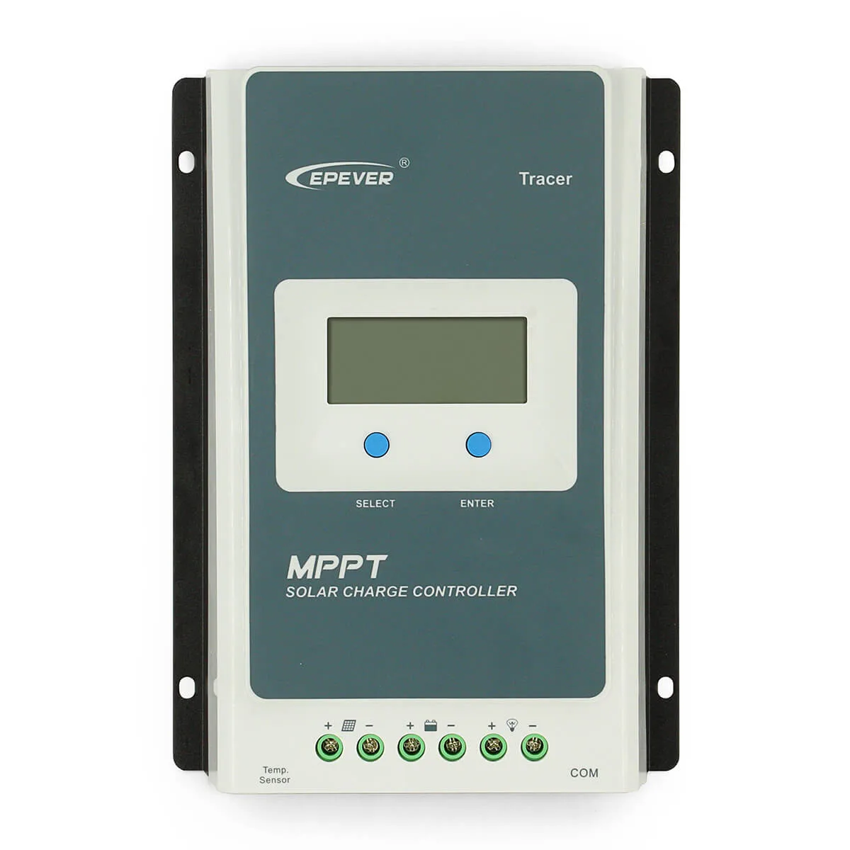


MPPT EPever Solar Charge Controller 40A 30A 20A 10A Tracer AN Series Back-light LCD Regulator for Lead-acid Lithium-ion Battery,can minimize the maximum power point loss rate and loss time,track the maximum power point of the PV array and obtain the maximum energy from solar modules under any conditions
|
Current Optional:
|
|


The Tracer AN series. Based on common negative design and advanced MPPT control algorithm, with LCD displaying running status, this product is artistic, economical and practical. Improving the MPPT control algorithm further, Tracer AN series can minimize the maximum power point loss rate and loss time, quickly track the maximum power point of the PV array and obtain the maximum energy from solar modules under any conditions; and can increase the ratio of energy utilization in the solar system by 10%-30% compared with a PWM charging method. The limitation function of the charging power and current and reducingcharging power function automatic improve the stability which works even connecting oversize PV modules and in high temperature, and increase the professional protection chip for the communication port, further improving the reliability and meeting the different application requirements.
Feature:
Advanced MPPT technology, with efficiency no less than 99.5%\Ultra-fast tracking speed and guaranteed tracking efficiency
Advanced MPPT control algorithm to minimize the maximum power point loss rate and loss time
Wide MPP operating voltage range
High quality components, perfecting system performance, with maximum conversion efficiency of 98%
Accurate recognition and tracking of multiple-peaks maximum power point
International famous brands of ST and IR's components of high quality and low failure rate are used, which can ensure the product’s service life
Charging power and current limitation function
Compatible with lead-acid and lithium-ion batteries
Battery temperature compensation function
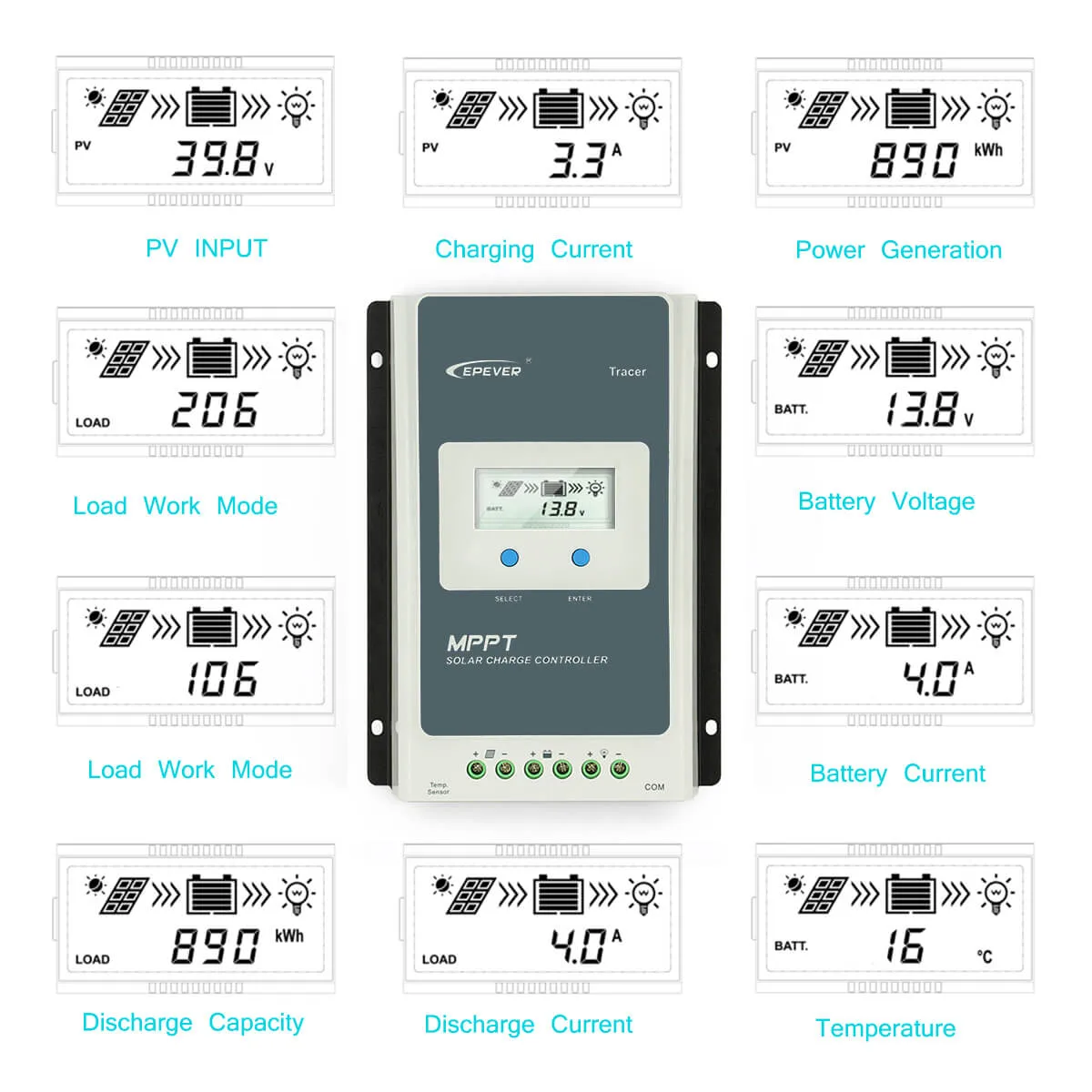
Real-time energy statistics function
Overheating power reduction function
Multiple load work modes
The communication port adopts professional protection chip, which can provide 5VDC power supply, and has over-current and short-circuit protection.
With RS-485 communication bus interface and Modbus communication protocol, it is available to meet various communication requirements in different situations.
Monitor and set the parameters via mobile phone APP or PC software
Full-load operation without any drop in capacity within the range of working environment temperature
Extensive electronic protection

1. Connect components to the charge controller in the sequence as shown above and pay much attention to the “+” and “-”. Please don’t turn on the fuse during the installation. When disconnecting the system, the order will be reserved.
2. After installation, power the controller and check the LCD on. If it’s not on, please refer to chapter 4. Always connect the battery first, in order to allow the controller to recognize the system voltage.
3. The battery fuse should be installed as close to battery as possible. The suggested distance is within 150mm.
4. The Tracer-A series is a positive ground controller. Any positive connection of solar, load or battery can be earth grounded as required.
Auto cycle interface

Browse interface

Battery Voltage Parameters (parameters is in 12V system at 25℃, please use double value in 24V.)
Battery charging setting | Sealed | Gel | Flooded | User |
Over Voltage Disconnect Voltage | 16.0V | 16.0V | 16.0V | 9~17V |
Charging Limit Voltage | 15.0V | 15.0V | 15.0V | 9~17V |
Over Voltage Reconnect Voltage | 15.0V | 15.0V | 15.0V | 9~17V |
Equalize Charging Voltage | 14.6V | —— | 14.8V | 9~17V |
Boost Charging Voltage | 14.4V | 14.2V | 14.6V | 9~17V |
Float Charging Voltage | 13.8V | 13.8V | 13.8V | 9~17V |
Boost Reconnect Charging Voltage | 13.2V | 13.2V | 13.2V | 9~17V |
Low Voltage Reconnect Voltage | 12.6V | 12.6V | 12.6V | 9~17V |
Under Voltage Warning Reconnect Voltage | 12.2V | 12.2V | 12.2V | 9~17V |
Under Volt. Warning Volt. | 12.0V | 12.0V | 12.0V | 9~17V |
Low Volt. Disconnect Volt. | 11.1V | 11.1V | 11.1V | 9~17V |
Discharging Limit Voltage | 10.6V | 10.6V | 10.6V | 9~17V |
Equalize Duration (min.) | 120 | —— | 120 | 0~180 |
Boost Duration (min.) | 120 | 120 | 120 | 10~180 |
Electrical Parameters
Model | Tracer1210AN | Tracer2210AN | Tracer3210AN | Tracer4210AN |
| Nominal system voltage | 12/24VDC auto work | |||
| Rated charge current | 10A | 20A | 30A | 40A |
| Rated discharge current | 10A | 20A | 30A | 40A |
| Battery input voltage range | 8~32V | |||
| Max. PV open circuit voltage | 100V(at minimum operating environment temperature) 92V(at 25℃ environment temperature) | |||
| MPP voltage range | VBAT+2V~ 72V | |||
| Max. PV input power | 130W(12V) 260W(24V) | 260W(12V) 520W(24V) | 390W(12V) 780W(24V) | 520W(12V) 1040W(24V) |
| Self-consumption | ≤12mA | |||
| Discharge circuit voltage drop | ≤0.23V | |||
| Temperature compensate coefficient | -3mV/°C/2V (Default) | |||
| Grounding | Common negative | |||
| RS485 interface | 5VDC/100mA | |||
| LCD backlight time | 60S (Default) | |||
| Storage temperature range | -20°C~+70°C | |||
| Working temperature | -25 ºC ~+50 ºC | |||
| Enclosure | IP30 | |||
| Overall dimension | 172x139x44mm | 220x154x52mm | 228x164x55mm | 252x180x63mm |
| Power terminals | 12AWG(4mm2) | 6AWG(16mm2) | 6AWG(16mm2) | 6AWG(16mm2) |
